Sunday 28 April 2013

Fuse box mount, propshaft bolts, diff oil, interior panels


Today 
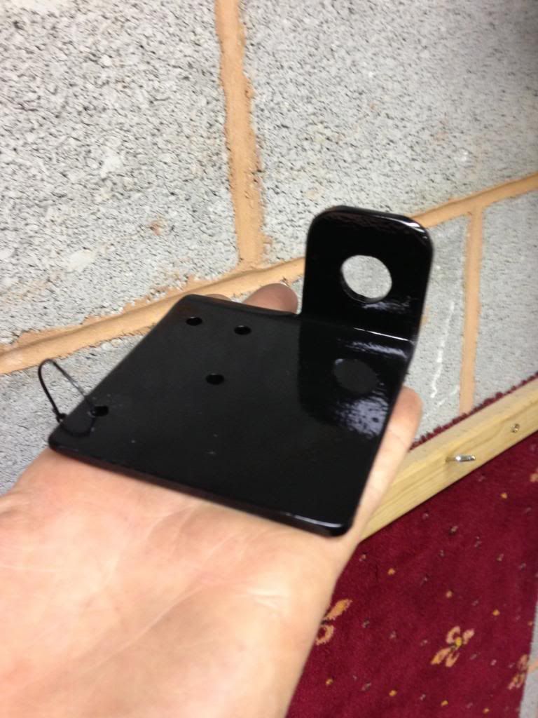
I had another full day in the garage doing various small jobs.  First job was to sort out where the fuses 
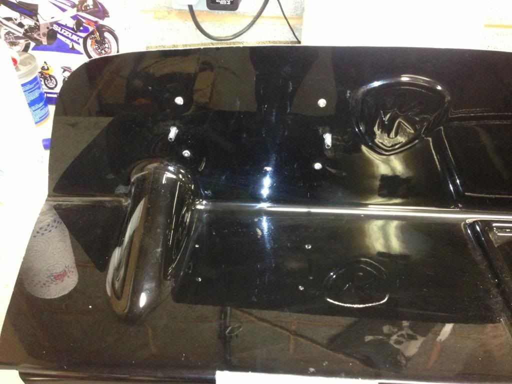
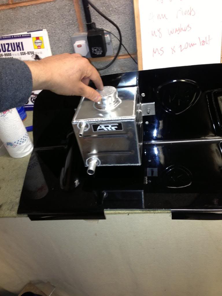
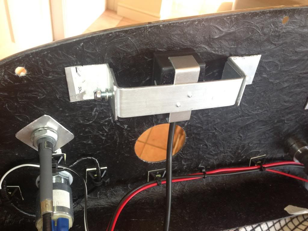
will be mounted.  I decided to mount them to the fiberglass bulkhead so they can be accessed from under the bonnet which 
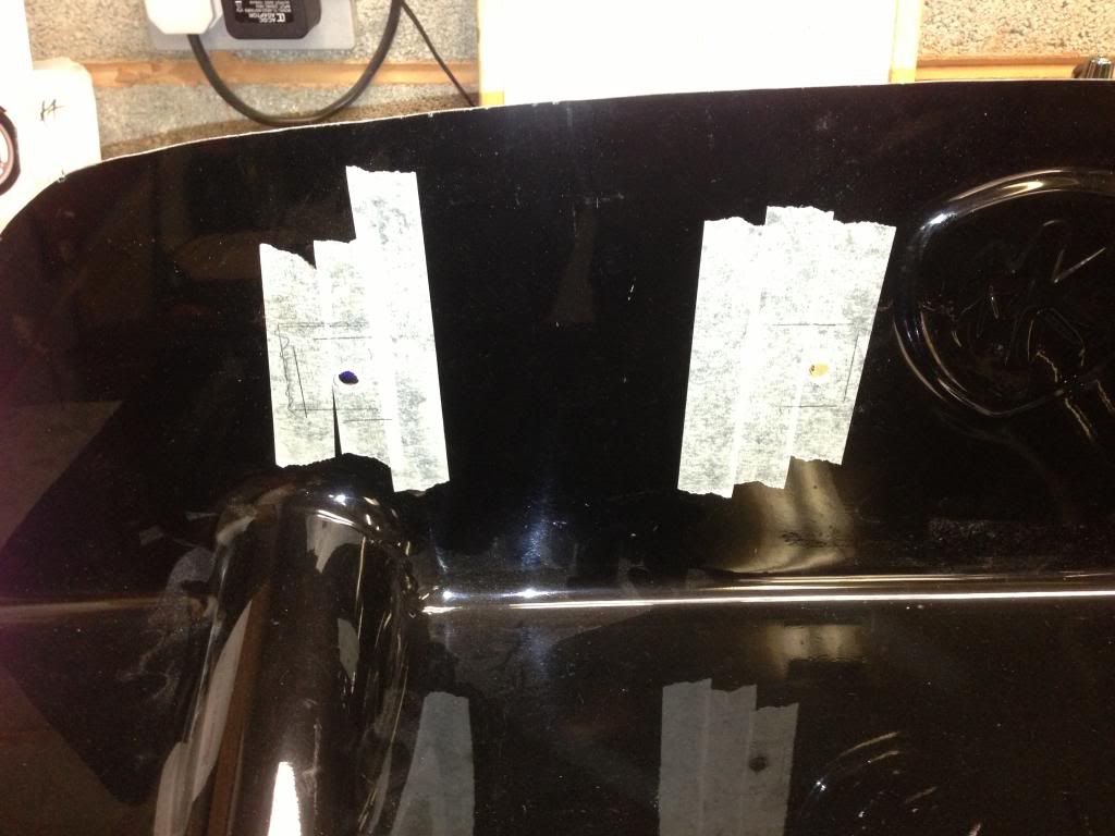
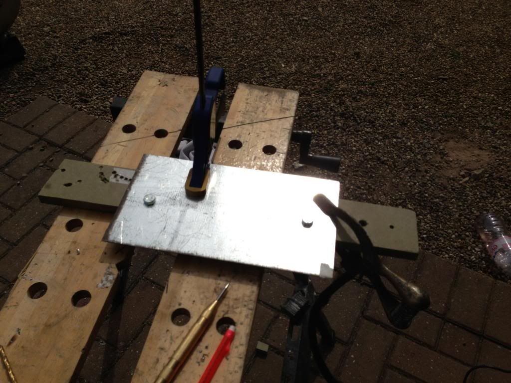
I prefer the look of compared to mounting them under the dash.  I marked the hole and drilled 2no 7mm holes 
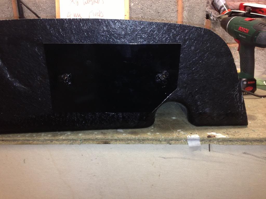
for the M5 rivnuts.  The hole was then cut out using the dremel.  I then cut a small length of edge trim to cover the edges (will need to be removed to get the fuse box through).

Next job was to fill the diff with oil.  The drain plug in the back of the diff should take a 10mm allen key but it appeared to be rounded so I couldn’t get it off. To begin with.  Fortunately I managed to undo it with a set of pipe grips.  I filled the diff with EP80w-90 gear oil using the tube that came with the bottle.  I had read online that it should take about 900ml but I put the whole bottle in and then checked the level using a bent piece of wire.  The level is about 10mm below the bottom of the drain hole which is exactly where it should be.
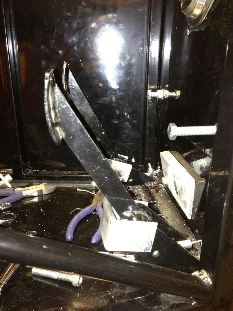
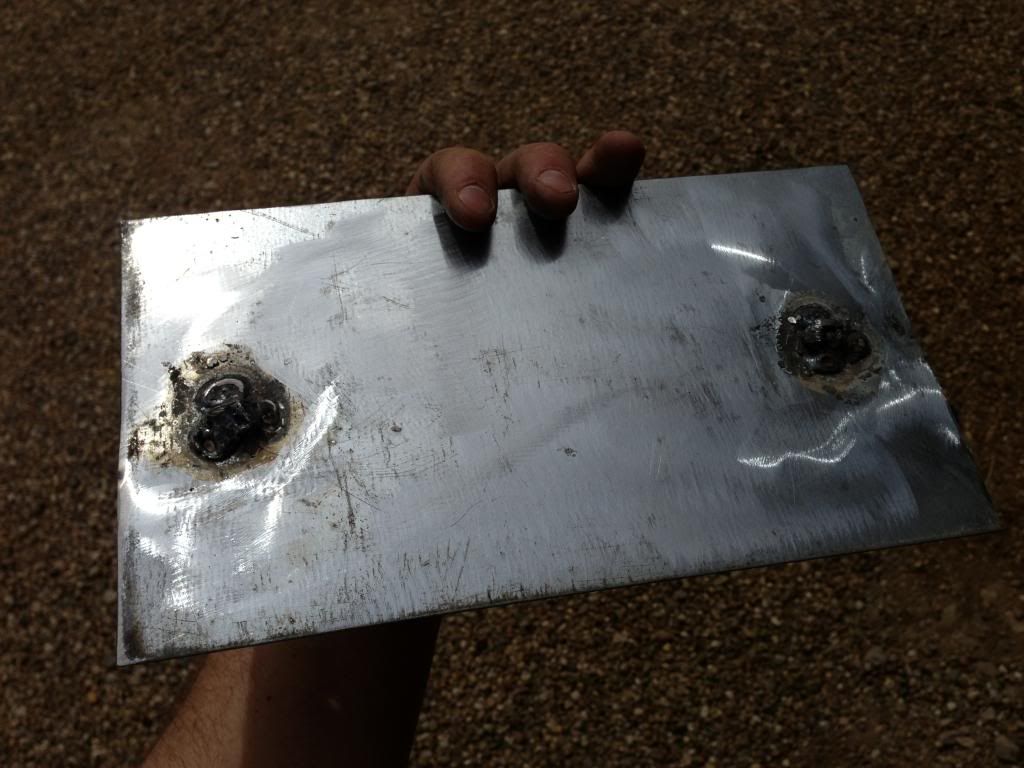
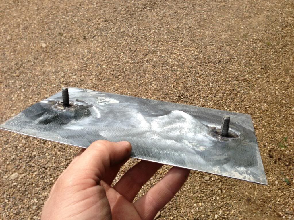
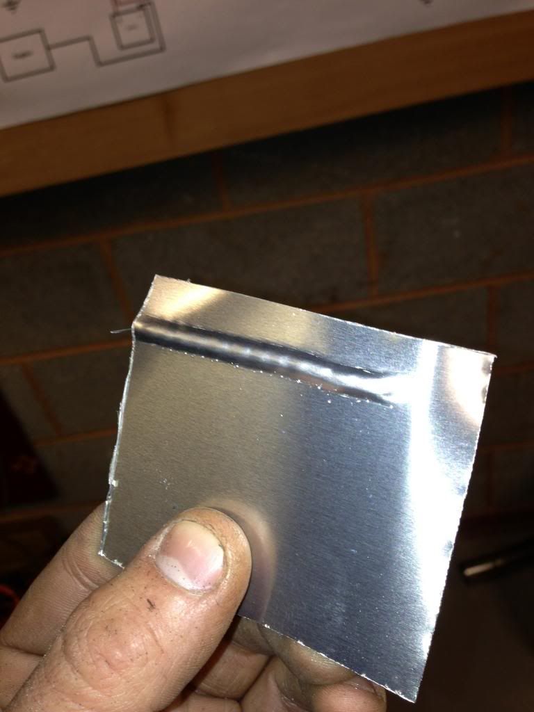
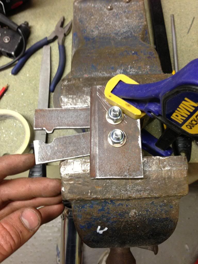
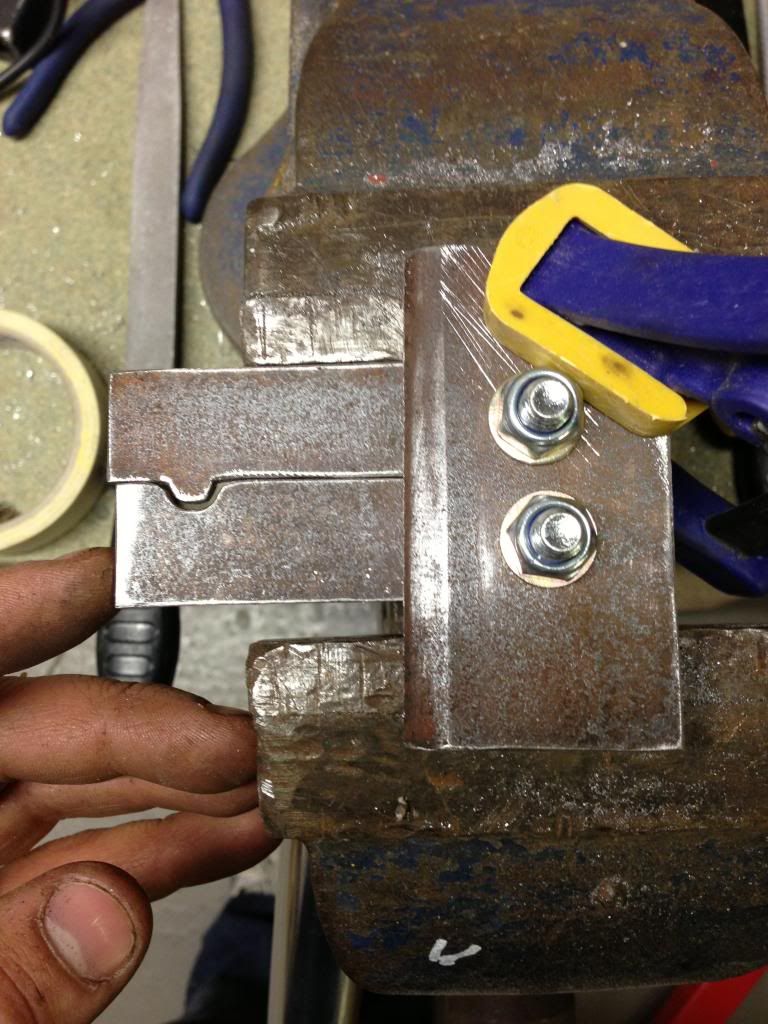
I then welded on the socket cap of an M12 bolt to the drain plug so it would be easier to remove in the future.

Final 
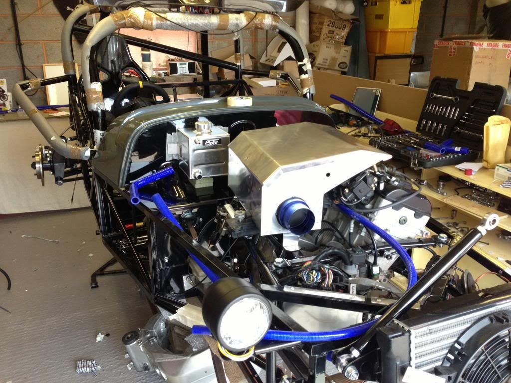
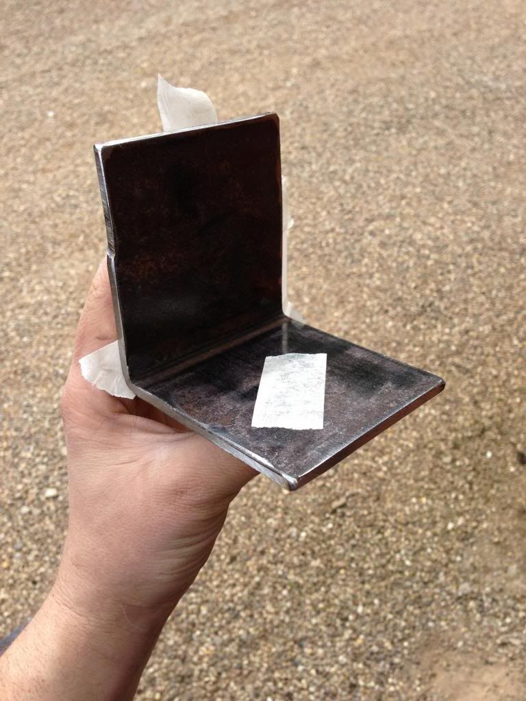
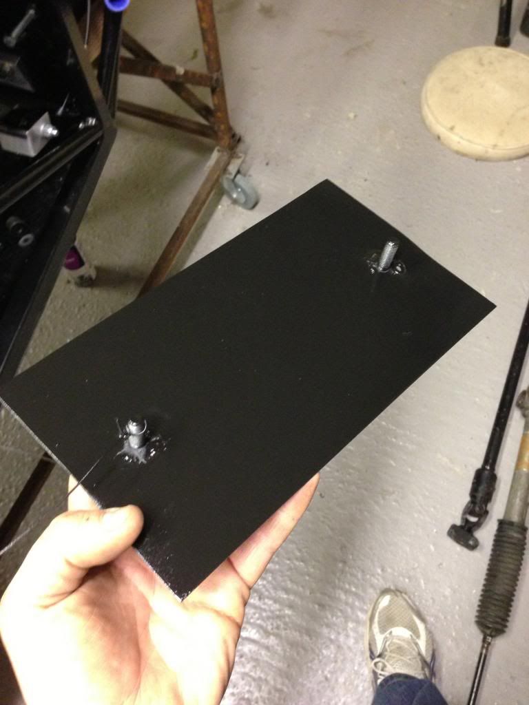
job for the day was to start on the interior panels.  The panels come almost cut to size from MK, a small bit of trimming is required.  I cut about 4mm off one side of the rear panel to get it to fit and then covered the top in edge trim as the edge was sharp and would be exposed.  The tunnel side panels were next and again some trimming was required along the back edge.  I then notched out for the seat rails and a couple of chassis rails.  I used the dremel with a diamond cutting disk which seemed to do a good job.

I still need to cut out for the harness bolts.


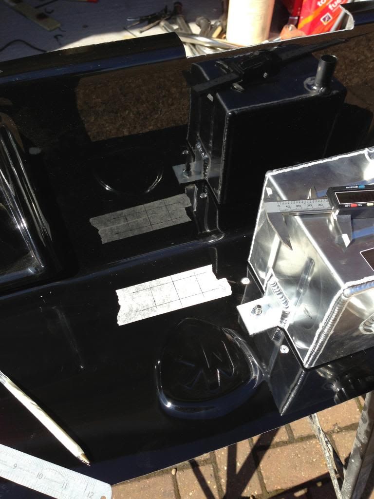
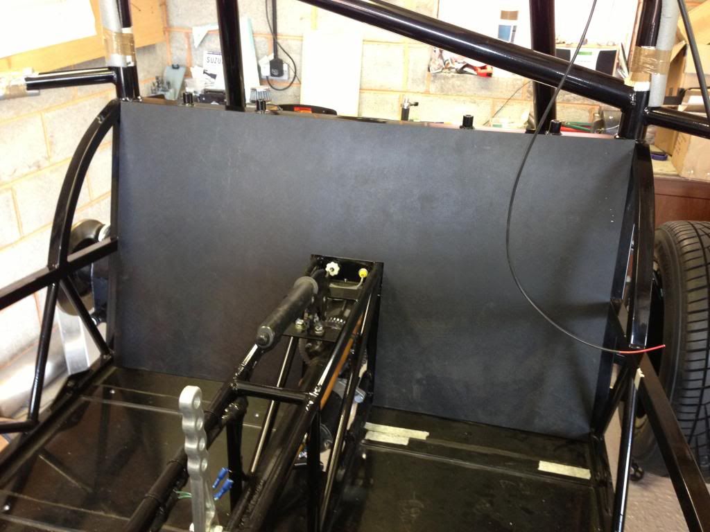
Hole marked for fuses

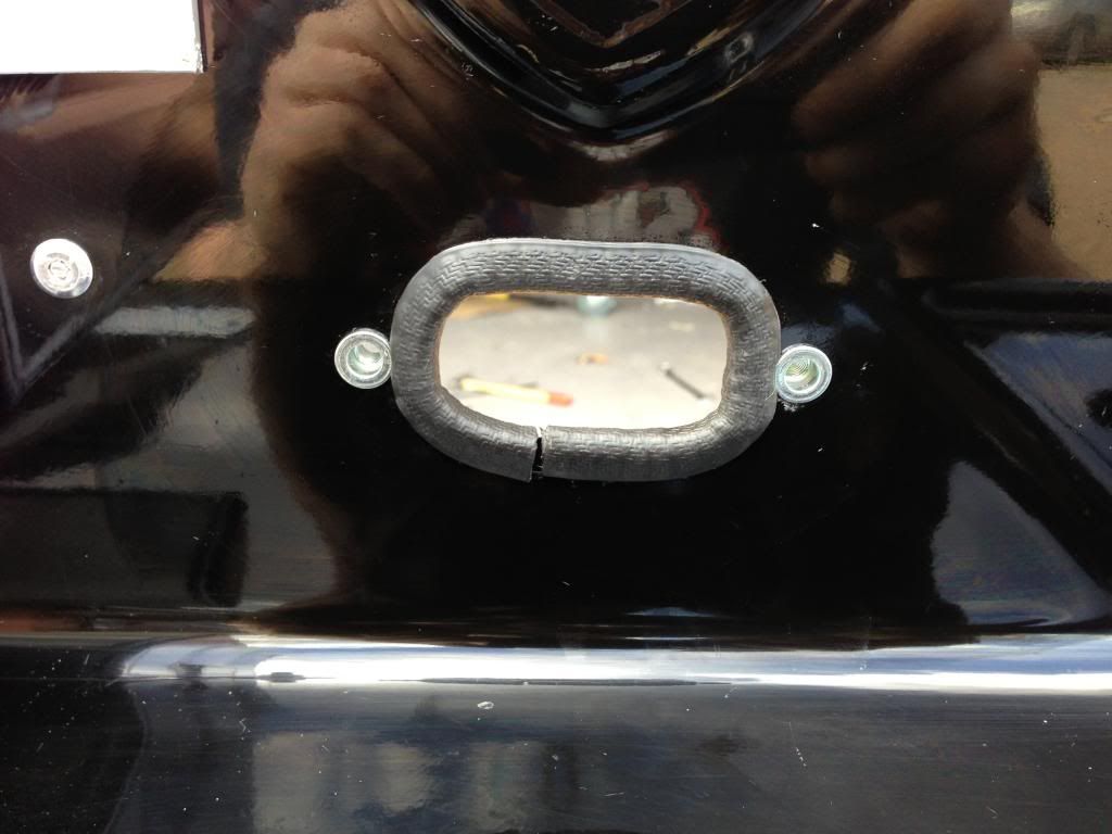
Fuse box mounting on fibreglass bulkhead

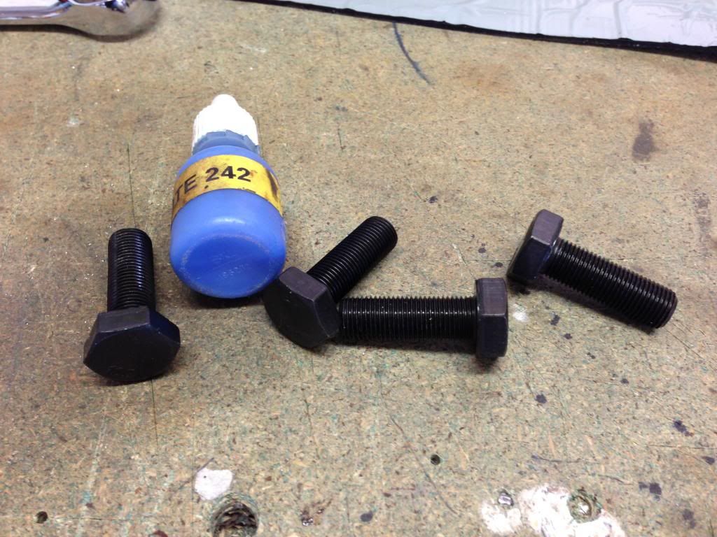
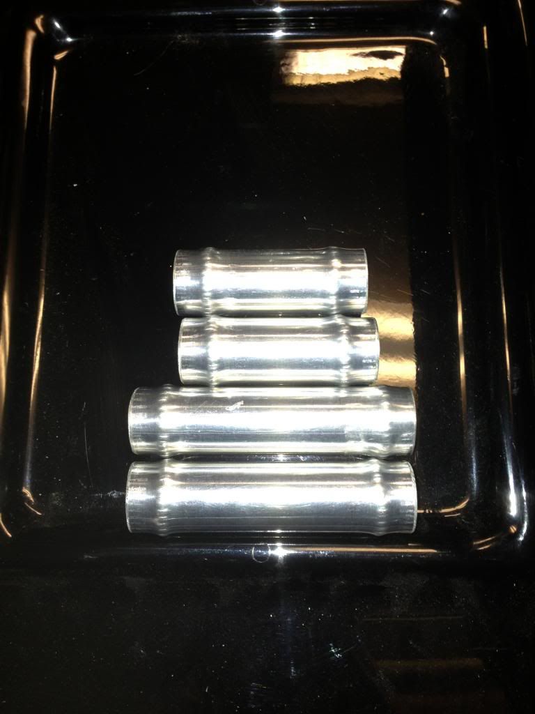
4no x M10 x 30 - fine pitch

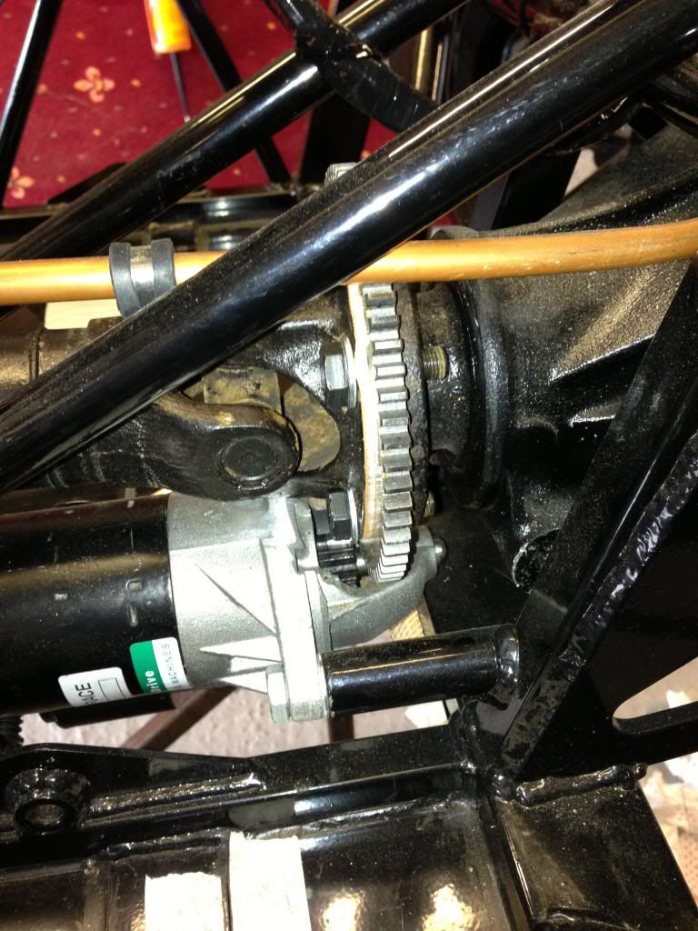
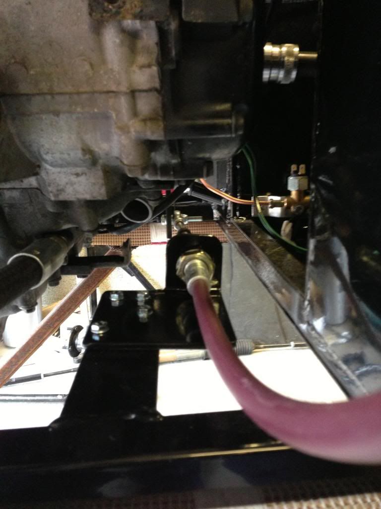
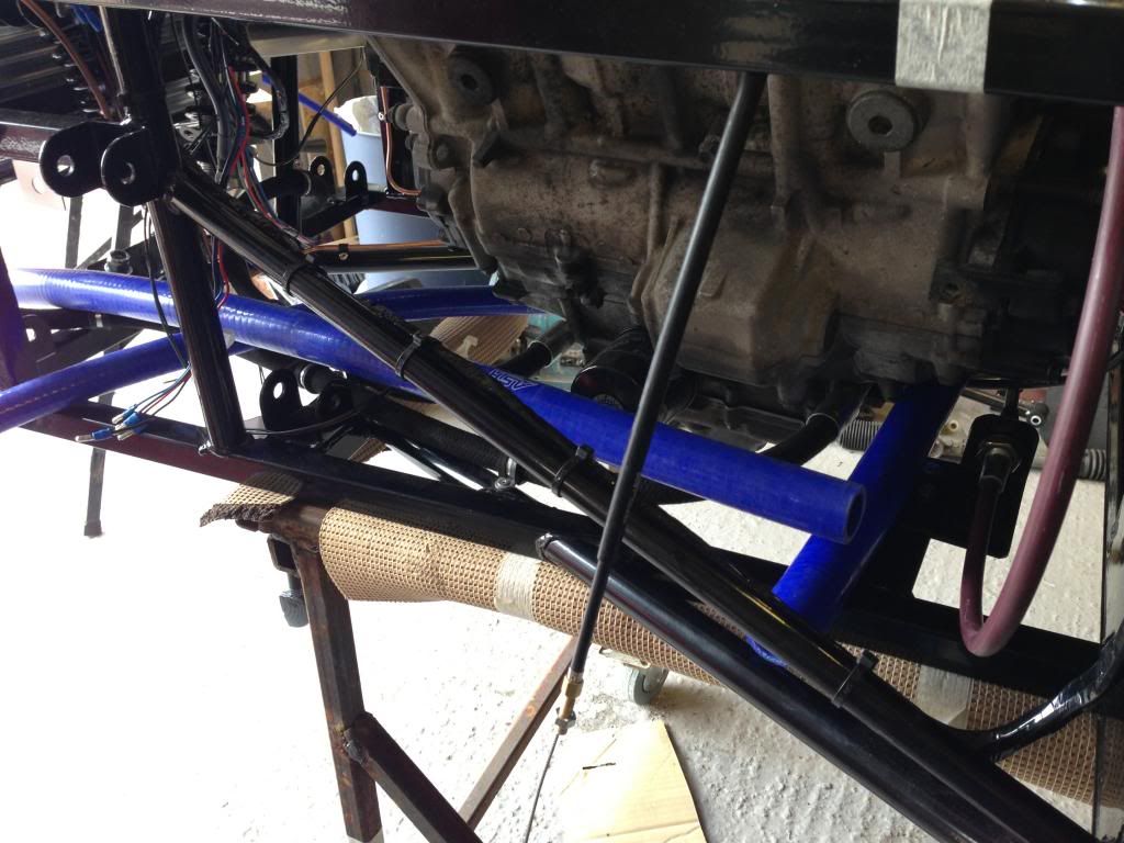
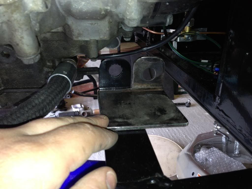
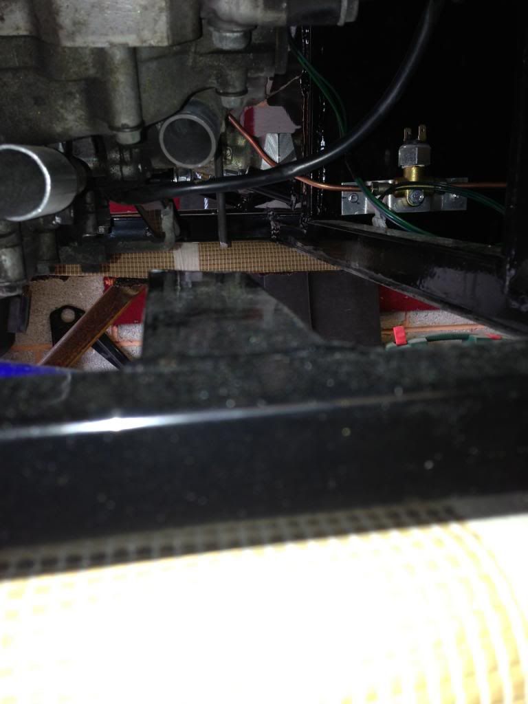
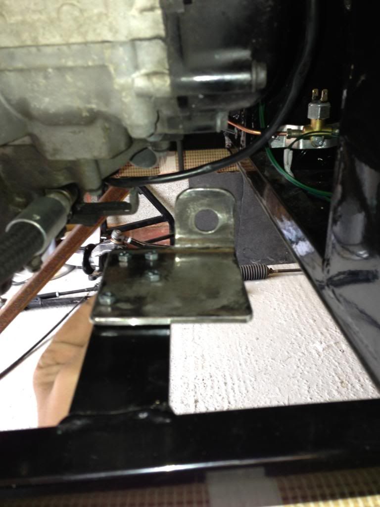
Prop to diff bolts in

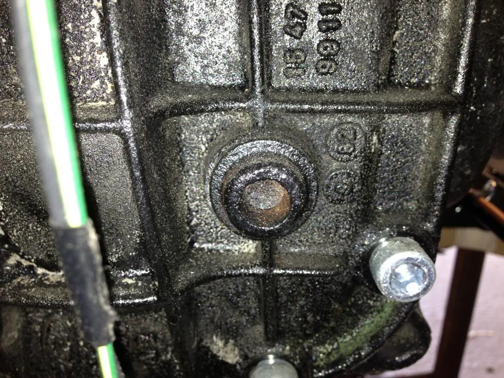
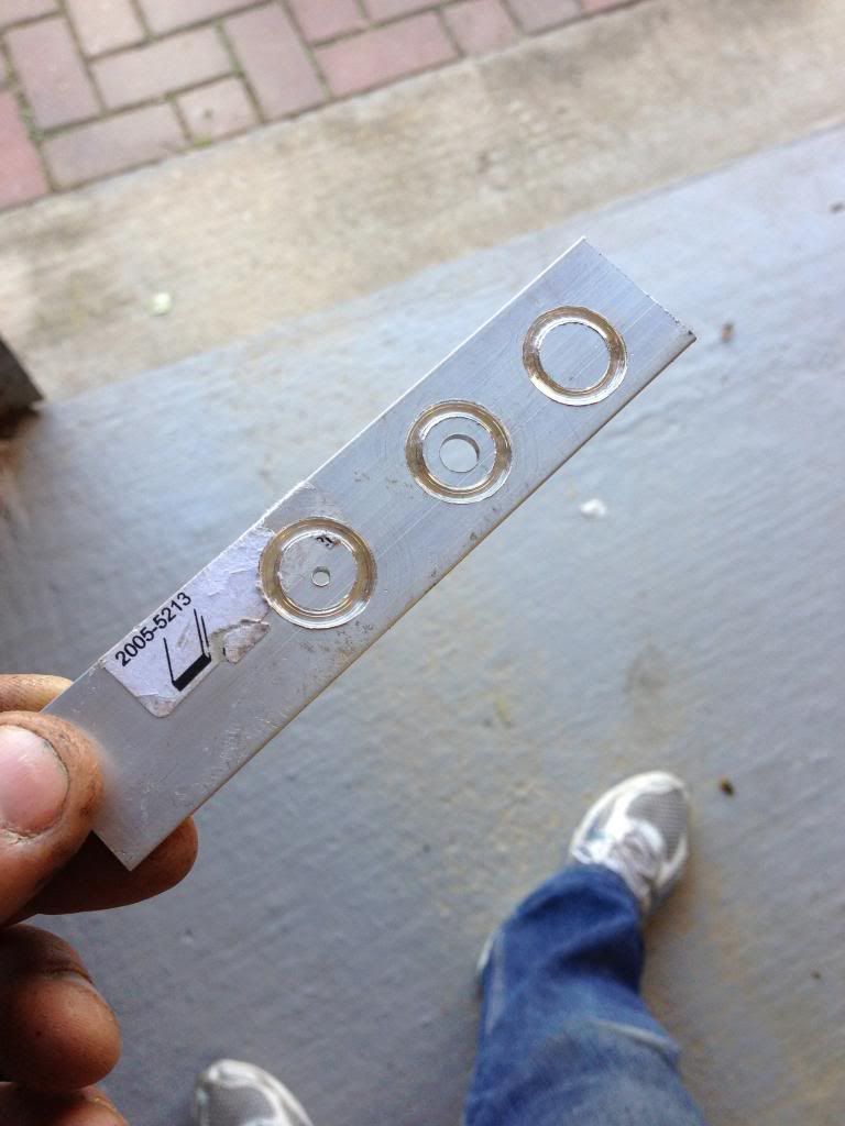
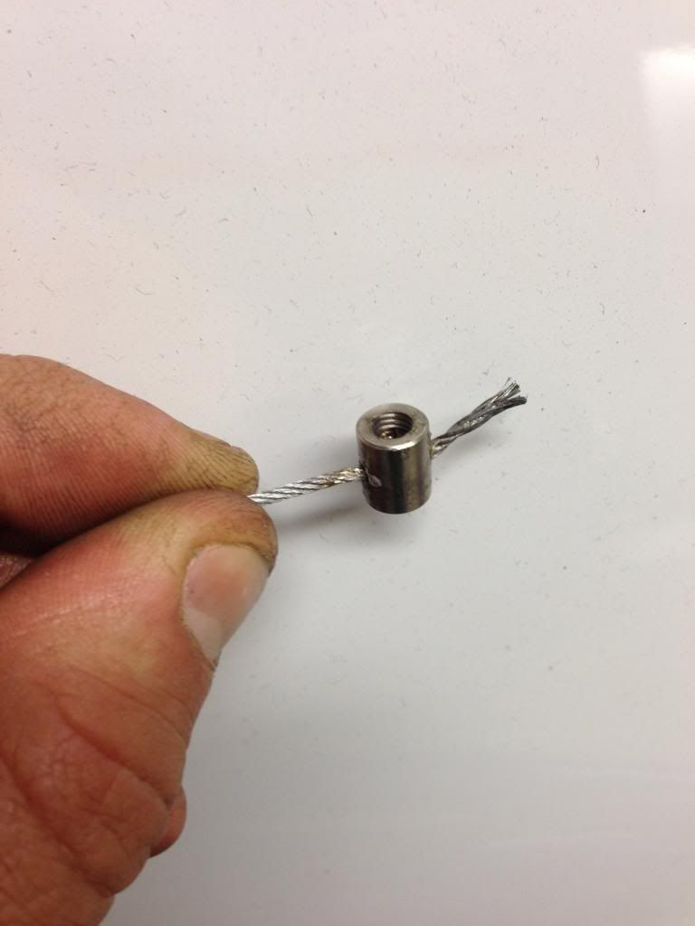
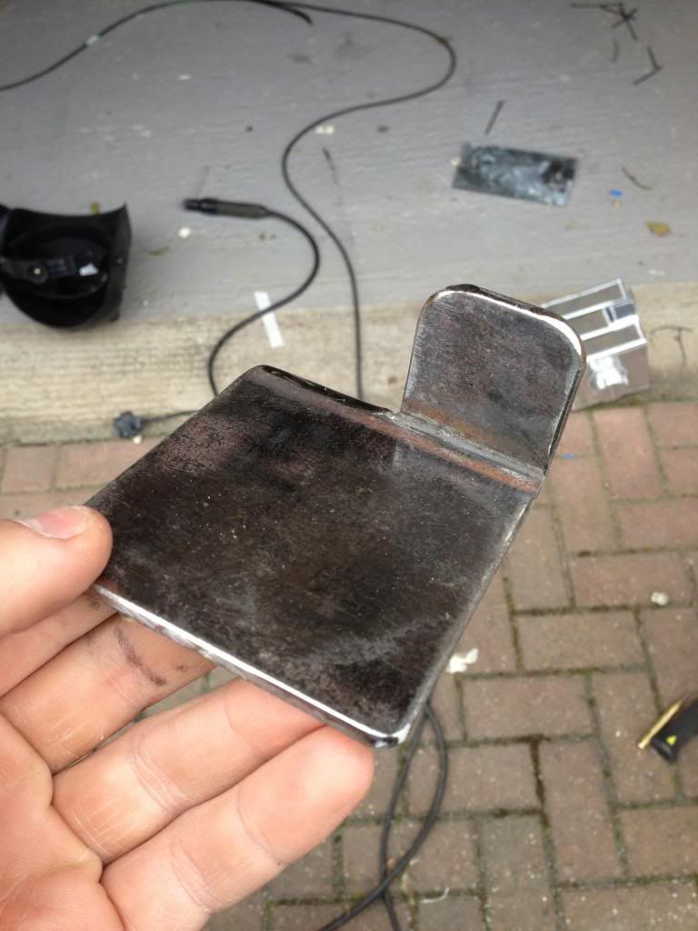
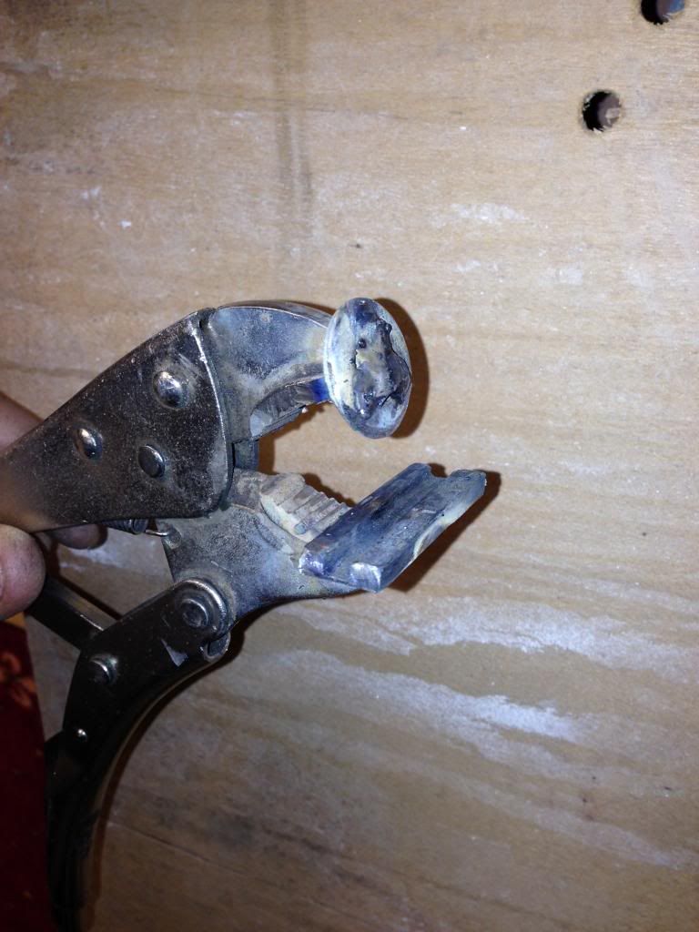
Drain plug rounded off

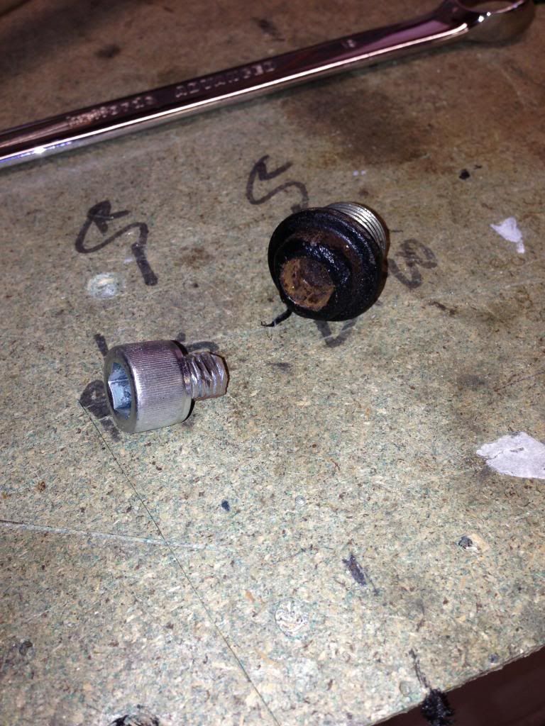
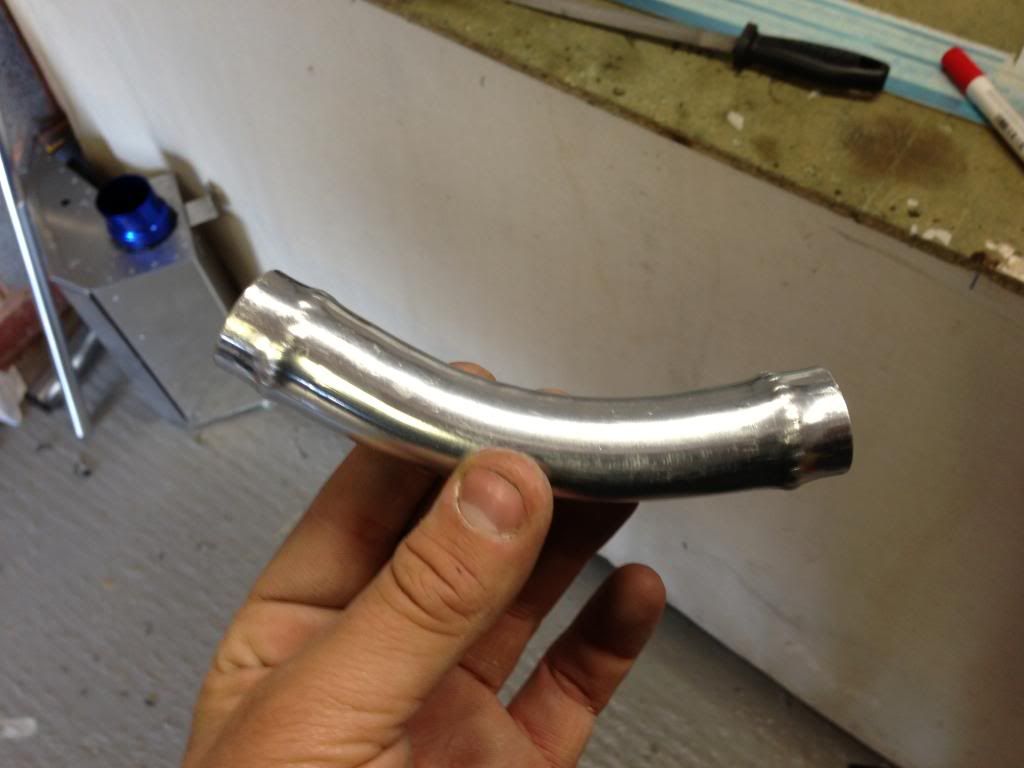
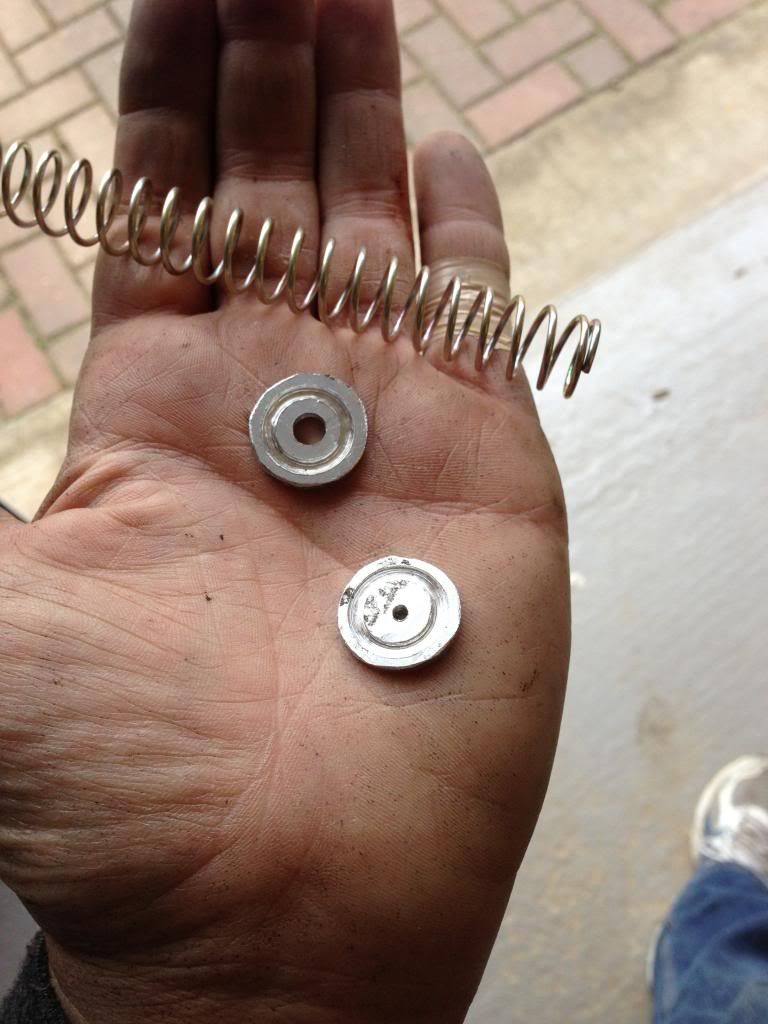
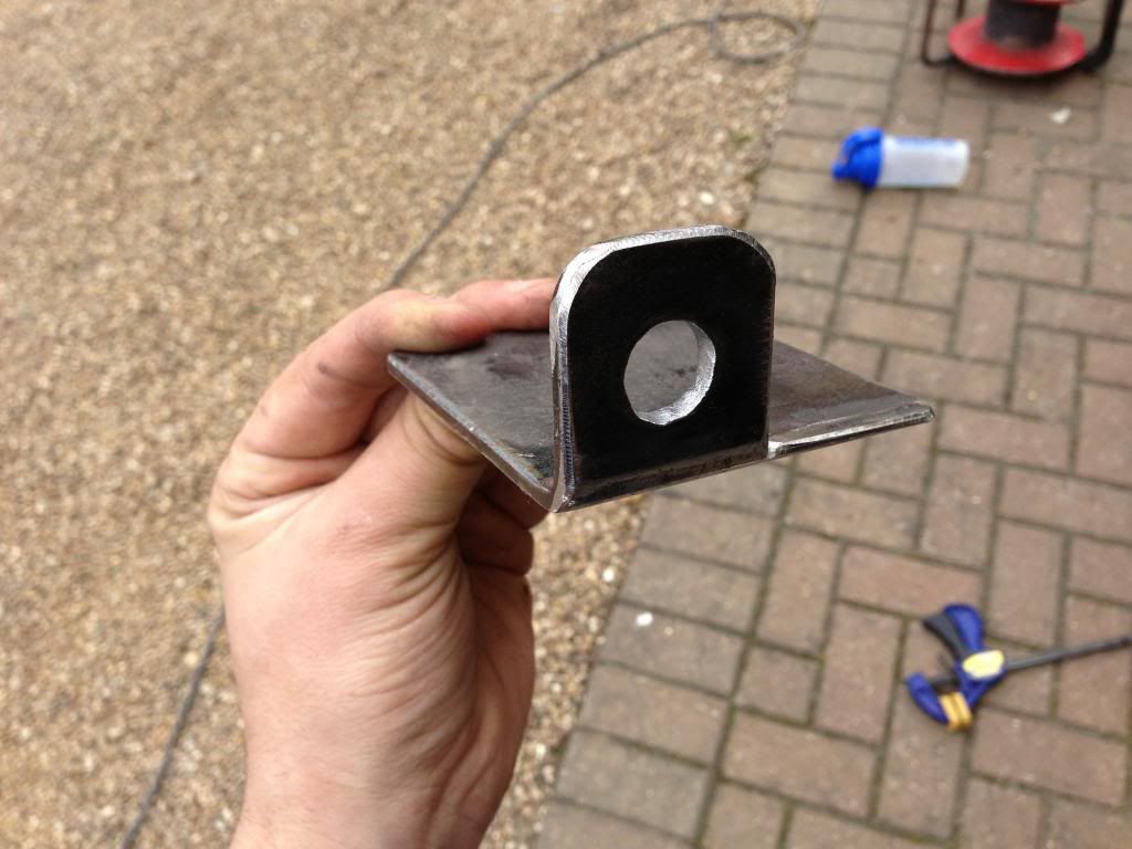
M12 socket cap bolt head to be welded

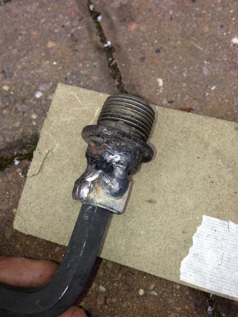
Welded to drain plug

Interior back panel cut to size


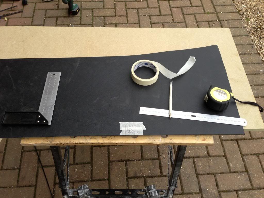
tunnel side panel marked for cutting


Saturday 27 April 2013

Cooling hoses and decelerator cable


My 25mm alloy pipe arrived today so I made a start on making connector pieces with beaded ends.  This worked well with my homemade beading tool.

I then bolted the new gearshift bracket in position so I could see how much room there would be for the hose to the water pump.  Next I laid out the silicone hoses to get the correct lengths before cutting. 

The hose from the thermostat to the top of radiator needed to bend quite a bit and when I tried with a straight length of hose, the hose would occasionally kink.  This wasn’t ideal so I remade a couple of the connector pieces but I made them curved (I did this by using a 25mm pipe bender).  Adding these two bends made the route a lot easier to make with silicone hoses.   I used a homemade P clip to secure the hose to the engine cradle.

I made another curved connector piece for the hose from the water pump, which will ensure that the hoses from the pump are not touching anything, so aren’t at risk from wearing through.

Last job was to start on the decelerator cable which will help close the throttle bodies and give better throttle feel.  I had seen an idea on Locostbuilders where a spring on the end of the cable could be used so I had a go at that.  I bought a set of compression springs from Screwfix and chose the one that would give enough tension – the spring was a bit long so I had to chop it down.  Next I made a couple of spring guides from 1.2mm aluminium.  The photos show how these are used, along with a cable clamp, to attach the spring to the end of the cable.  I need to make some adjustment to the throttle cable as the decelerator cable now stops the throttle opening all the way.

Connector pieces with beaded ends

New gearshift bracket fitted.  Cable in position

Hoses laid out in position

Curved connector with beaded ends

Top hose complete

Top hose in position


Top of radiator.  8mm outlet capped off

Spring guides.  Used a holesaw without drill bit to cut halfway through aluminium

Guides cut out


Fitted to decelerator cable


Wednesday 24 April 2013

Expansion tank mounting


It turns out the 25mm pipe I ordered is actually 28.5mm OD so with the bead is near 30mm….. a bit too large for a 25mm silicone hose.  I need to get the right size pipe.

Tonight I installed the mounting plate for the expansion tank.  I marked and drilled 2no M8 holes in the bulkhead panel, then a further 4no 5mm holes for the rivets.  The mounting panel was then rivet in position – I used skiaflex too for a strong bond.

Hopefully when the bulkhead is fixed to the scuttle this will be strong enough to support the weight of the expansion tank with water in it.  If not then I will add a support bracket underneath the tank.


Tuesday 23 April 2013

Clutch pedal

I bought a new 8mm solderless nipple for the end of the clutch cable as the first one came loose some weeks ago.  The new one has a grub screw with a point as opposed to just a bolt that the last one had which should hold the cable better.

I decided to solder the end on as well as clamping it with the grub screw.  To do this I pulled the cable through, frayed the ends slightly, applied some flux, pulled the cable back into the nipple, tightened it and soldered it.  When soldering I heated the nipple directly, not the cable as I didn’t want to damage the cable.  Once the flux was boiling I applied the silver solder and it ran into the nipple and filled around the cable.  The excess cable was then cut flush with the dremel.

Next I installed the adjusters to the sprocket cover and to the bulkhead, cut the outer part to length and threaded that onto the cable.  I then held the pedal in position to determine where on the cable the clevis would be fixed.  The clevis is held in position by two grub screws to which I applied Loctite.  I also doubled the cable back on itself and fixed it with a cable clamp just to be sure it wouldn’t come loose.

I also installed front and back cable stops, exactly the same as with the throttle pedal.


Sunday 21 April 2013

Gear indicator, gearshift bracket, expansion tank bracket


First job was the gear indicator.  I bolted the bracked to the angle pieces I stuck to the dash yesterday.  This holds the gear indicator in position and no fixings can be seen.

Next, having decided on the position of the header tank (to the side of the steering column), I needed to decide how to mount it.  I thought that simply fixing to the fiberglass wouldn’t be strong enough and would run the risk of the fixings coming loose so I made a bracket that will fit behind the fiberglass and spread the load.  I used some 1mm steel plate, drilled holes in it to match the holes n the header tank and welded 2no M8 bolts into it.  This will eventually be fixed behind the fiberglass with sikaflex so that only the two bolts can be seen sticking through for the tank to bolt to.

Next job was the gearshift bracket.  I chopped up a piece of 4” hollow square section and made the bracket similar to what was on the chassis originally but offset 40mm.  I drilled 4no 5mm holes to bolt the new bracket to the original.

Then I tried to made a beading tool to put a bead on the alloy tube that will join the silicone hoses together (the bead is needed to stop hoses coming undone.  I had seen a couple of ideas on Locostbuilders and the first one I tried was a modified set of molegrips.  This idea worked well on 1.2mm sheet aluminium but didn’t work on the much tougher alloy hose.  I then made another beading tool from scratch, again from an idea I had seen on Locostbuilders but this one used the vice to press so had must more force behind it.  This did a decent job of pressing in a bead, expanding the tube by about 1.5mm which should be plenty to stop the hoses sliding off.


Proposed position of expansion tank


Piece of 4" square section


16mm hole for gear shift cable

New and existing brackets together

Existing bracket end cut off.  Looks like theres loads of room for cooling hose now!

4no. M5 bolts foxing bracket in position.  Holes offset due to stiffener under bracket

Pipe beading tool made from pair of mole grips

Works well on 1.2mm aluminium.  Didnt work on tougher alloy tube

2nd attempt at beading tool - open position


closed position

gear shift bracket painted

expansion tank bracket painted