Sunday 31 March 2013

Electric reverse fuse and mounting brackets for GSXR clocks


Today I started tidying up the electrics.  I 
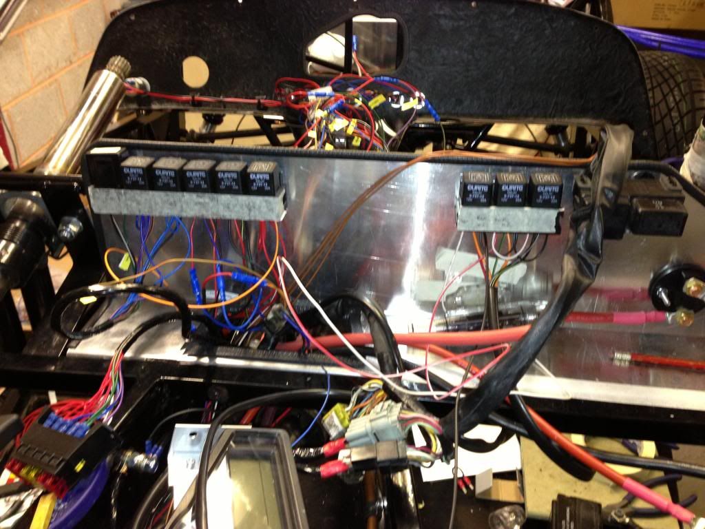
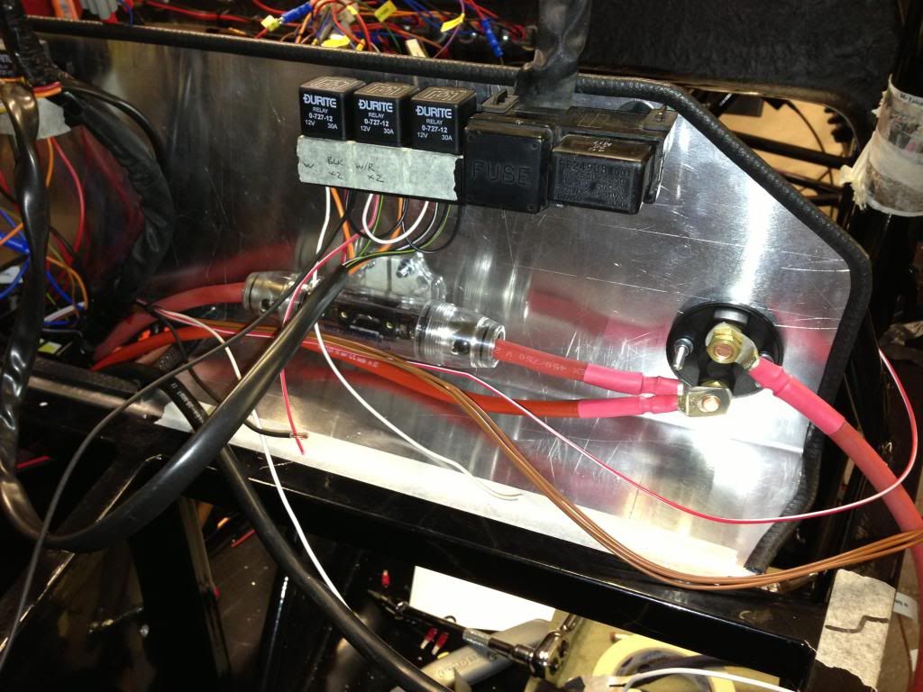
installed a 150A inline fuse for the reverse motor – this was an old one I had from my car audio system about 10 years ago.  I cut into the 25mm2 red cable and installed the fuse, bolting it to the aluminium under the scuttle.  I also 
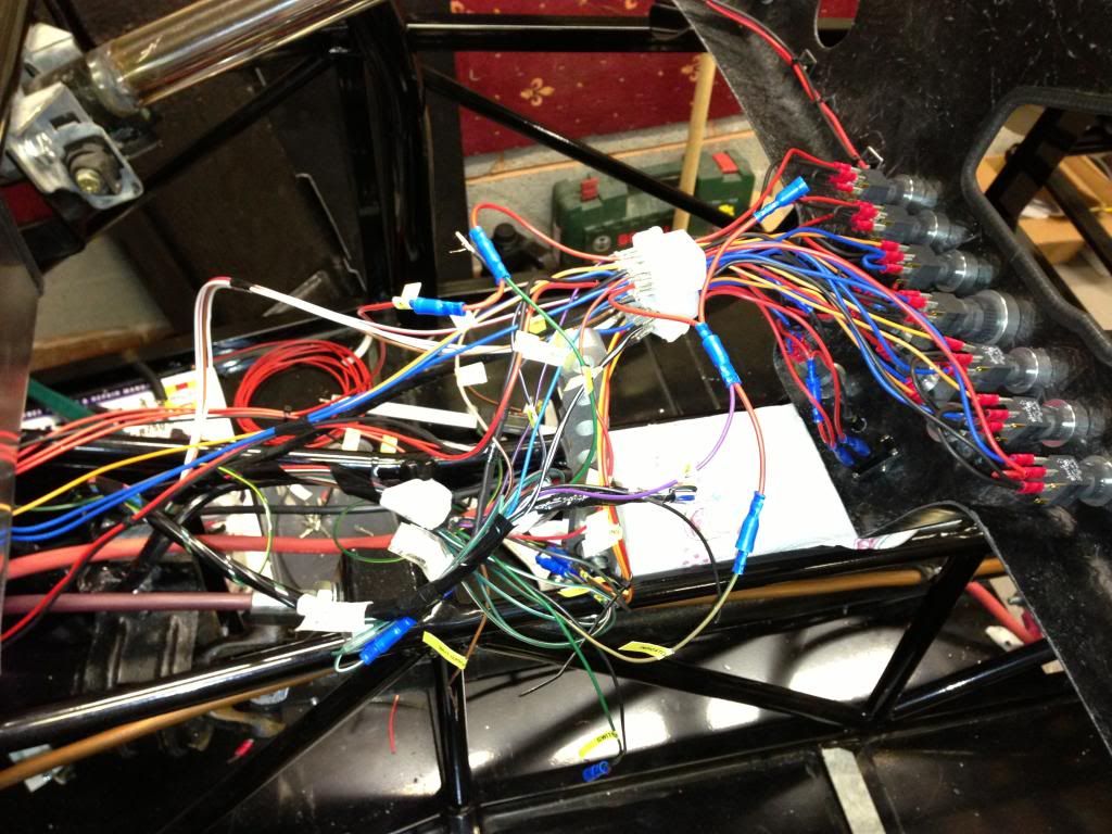
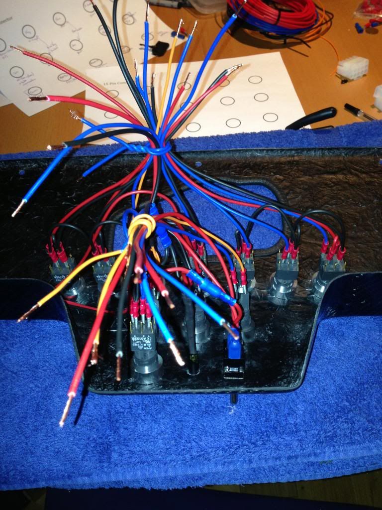
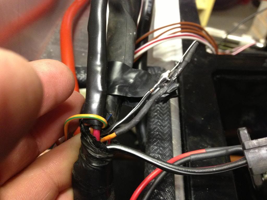
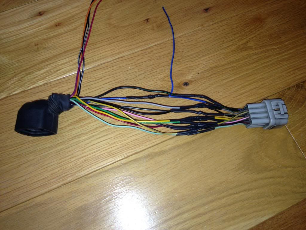
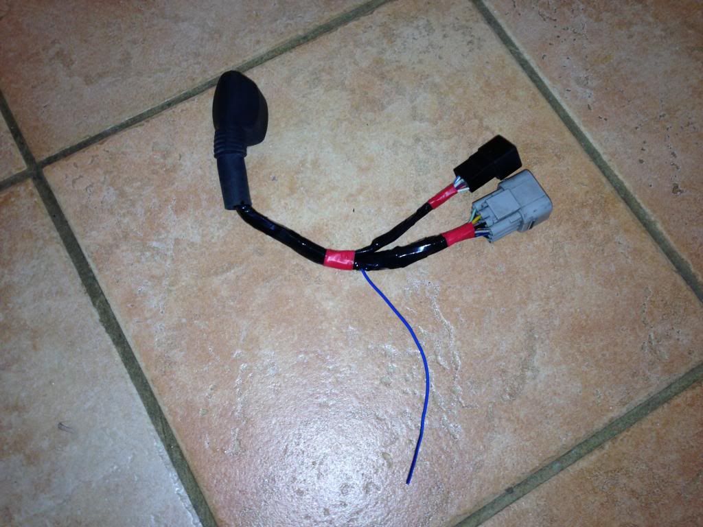
completed the 15 pin connector wiring, last ones to sort were for the reverse.

I 
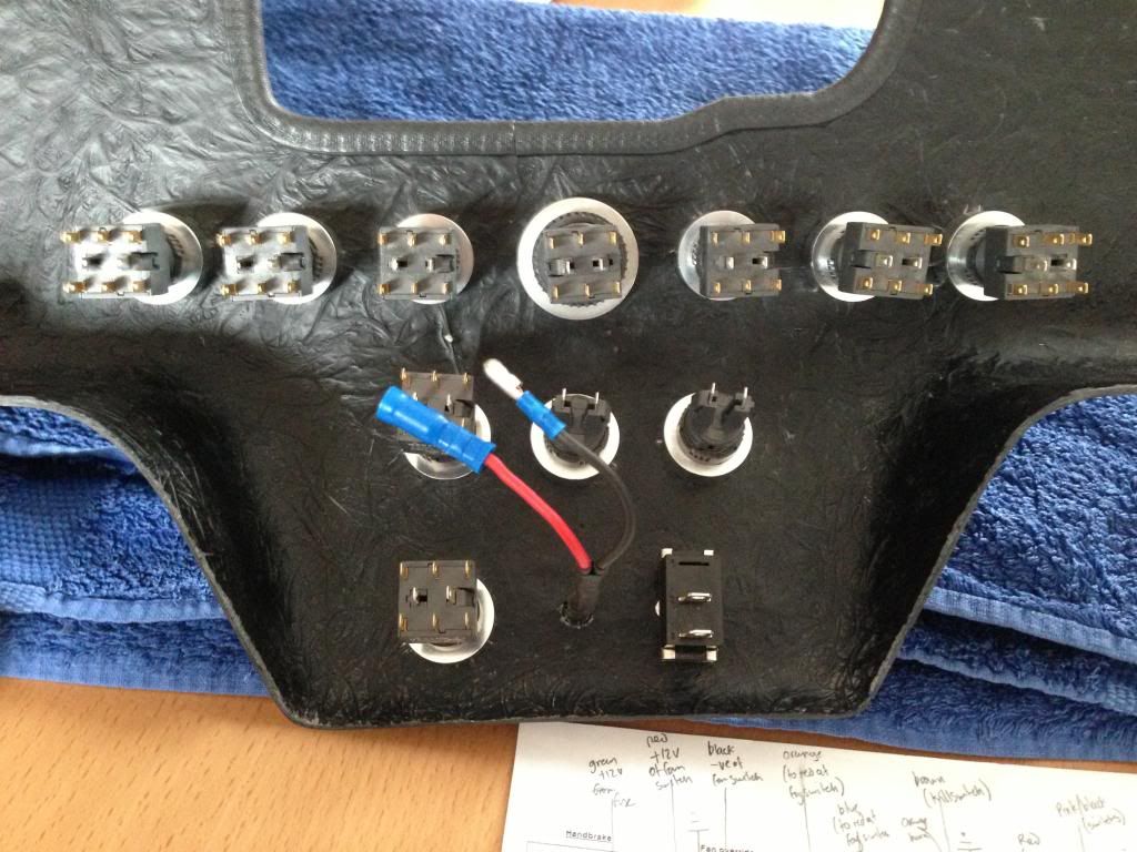
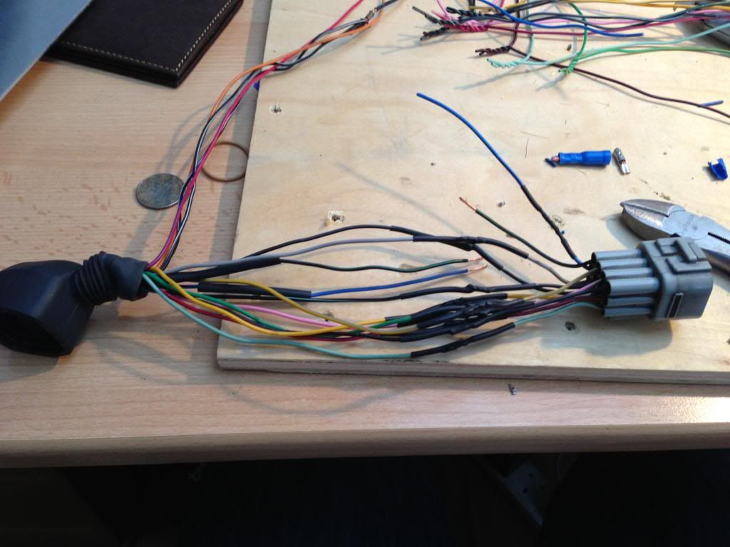
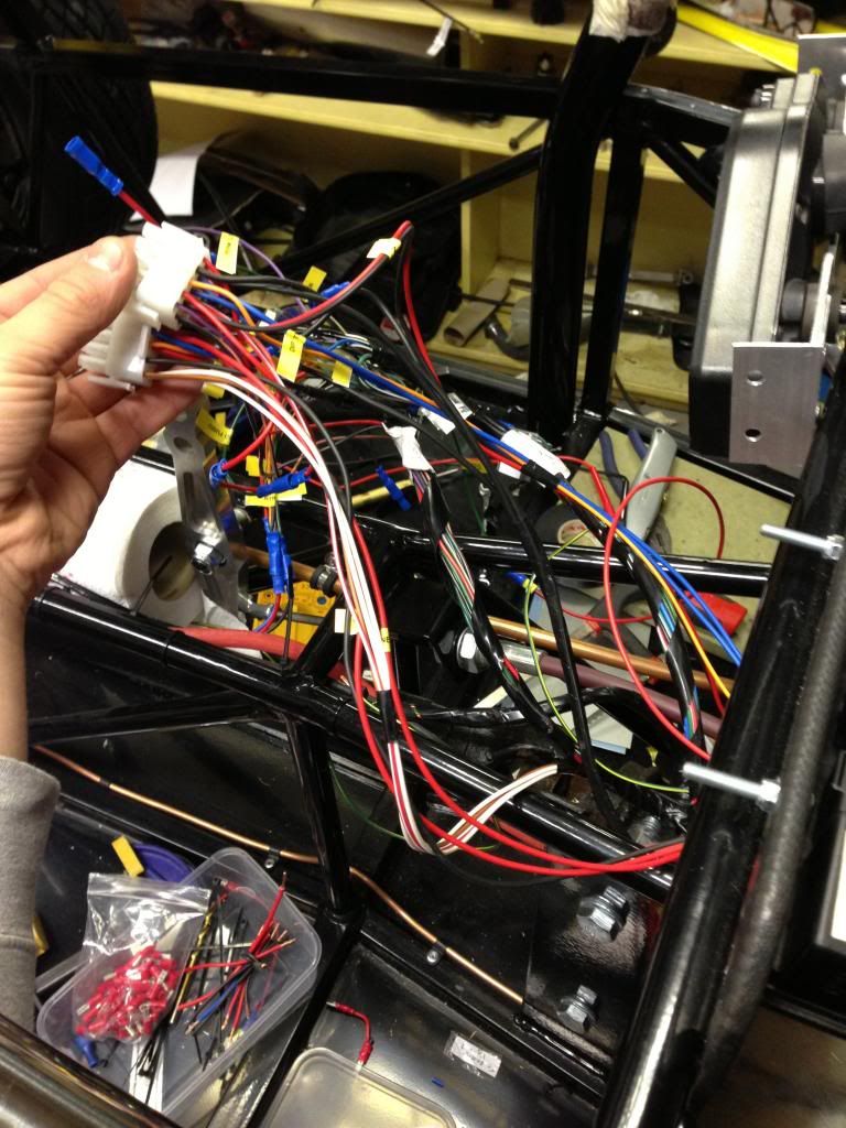
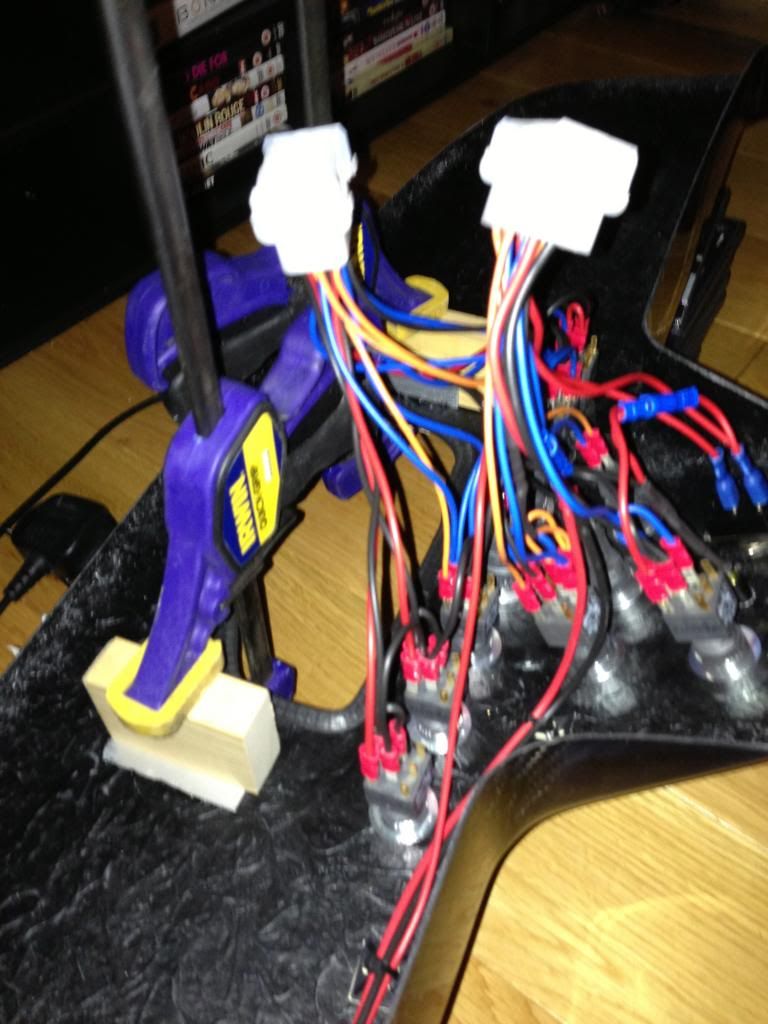
then soldered up all the male ends for the 15 pin connectors.  I did this one at a time, removing one, soldering, writing position, function and wire colour on my drawing before installing to the connector block.


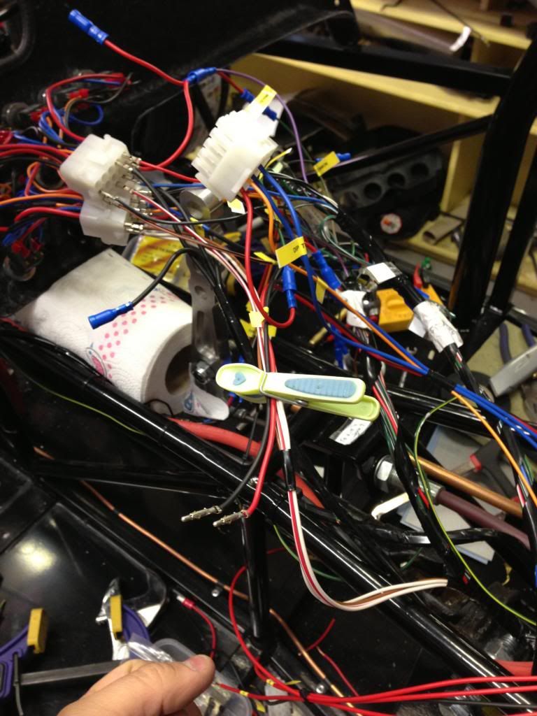
Soldering the terminals for the 15 pin connectors

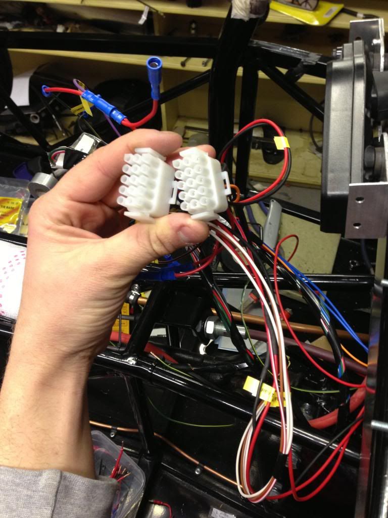
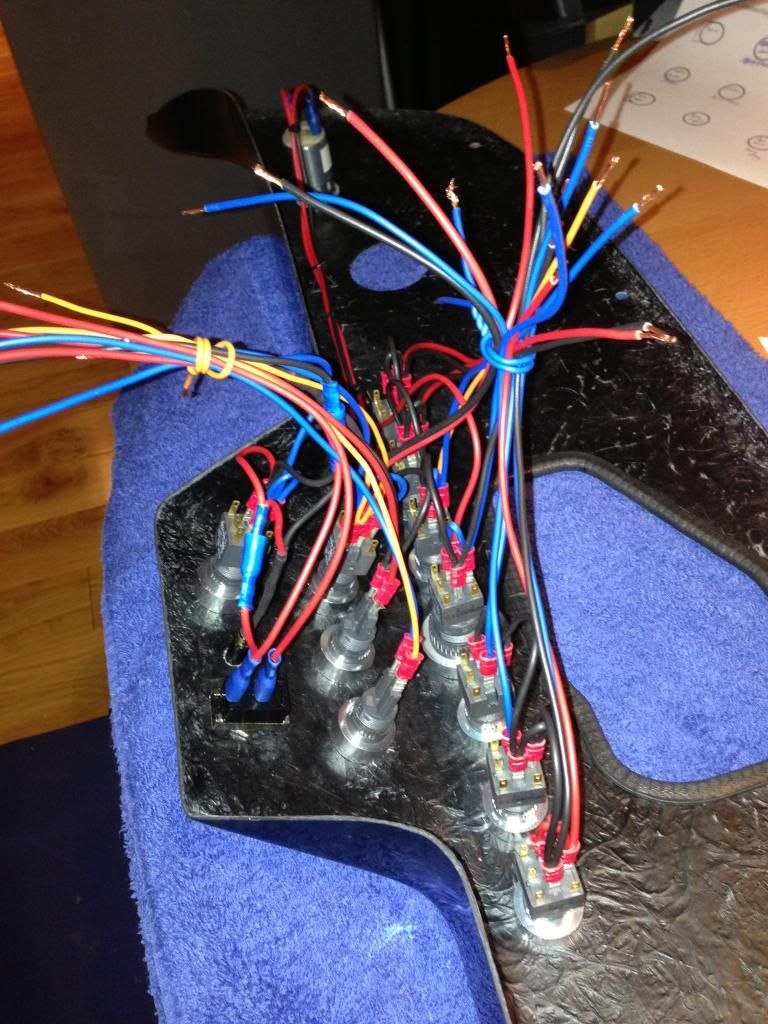
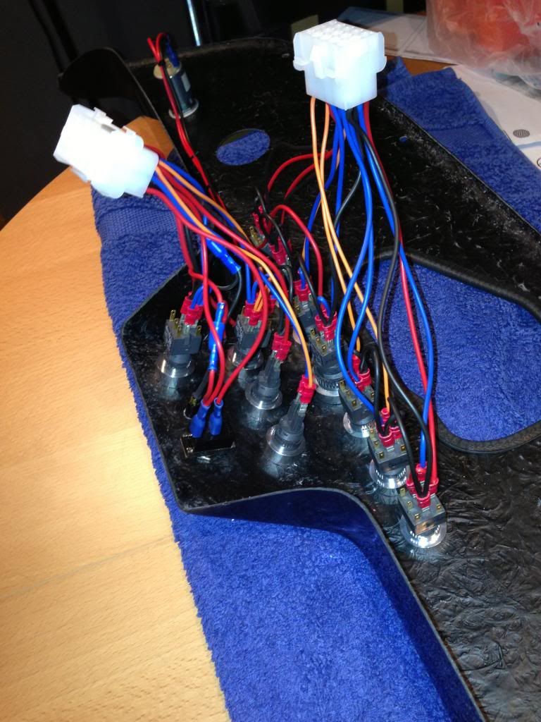
Connector blocks finished


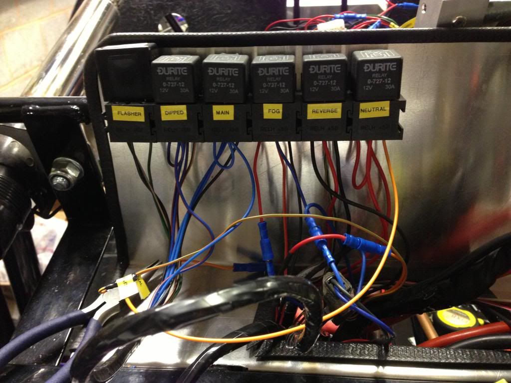
Relays labelled for reference


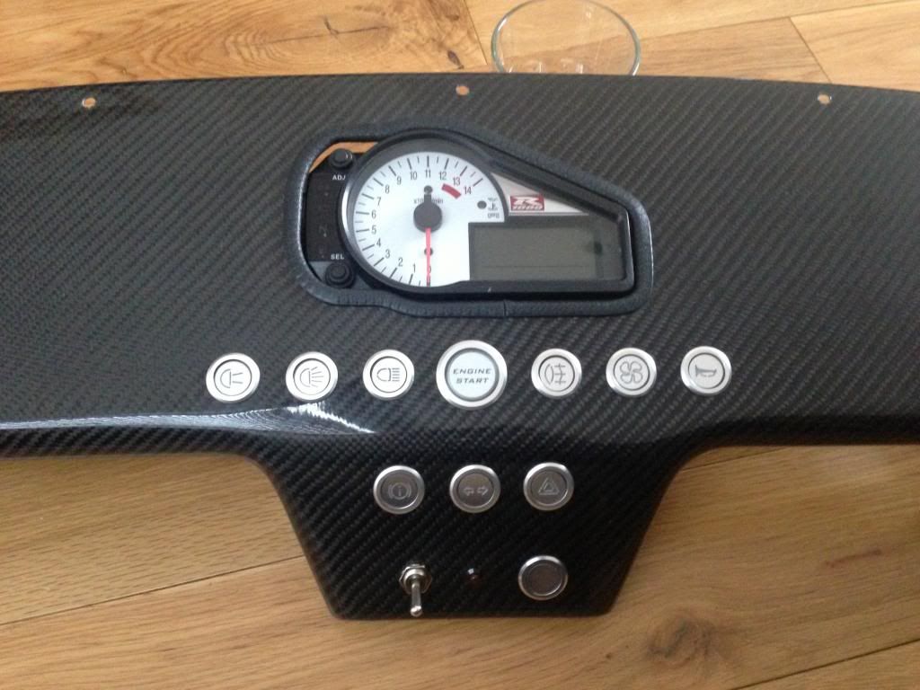
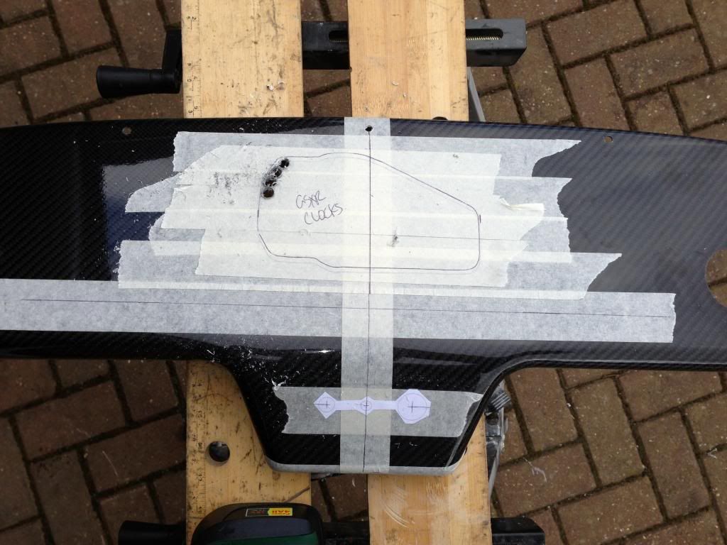
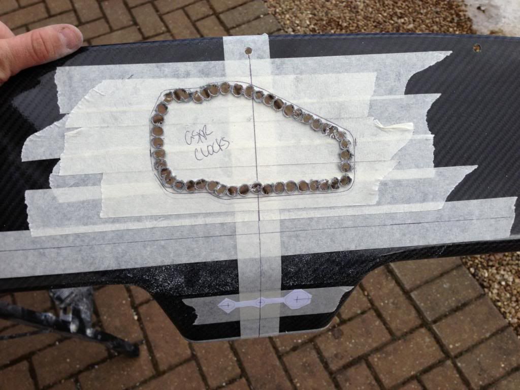
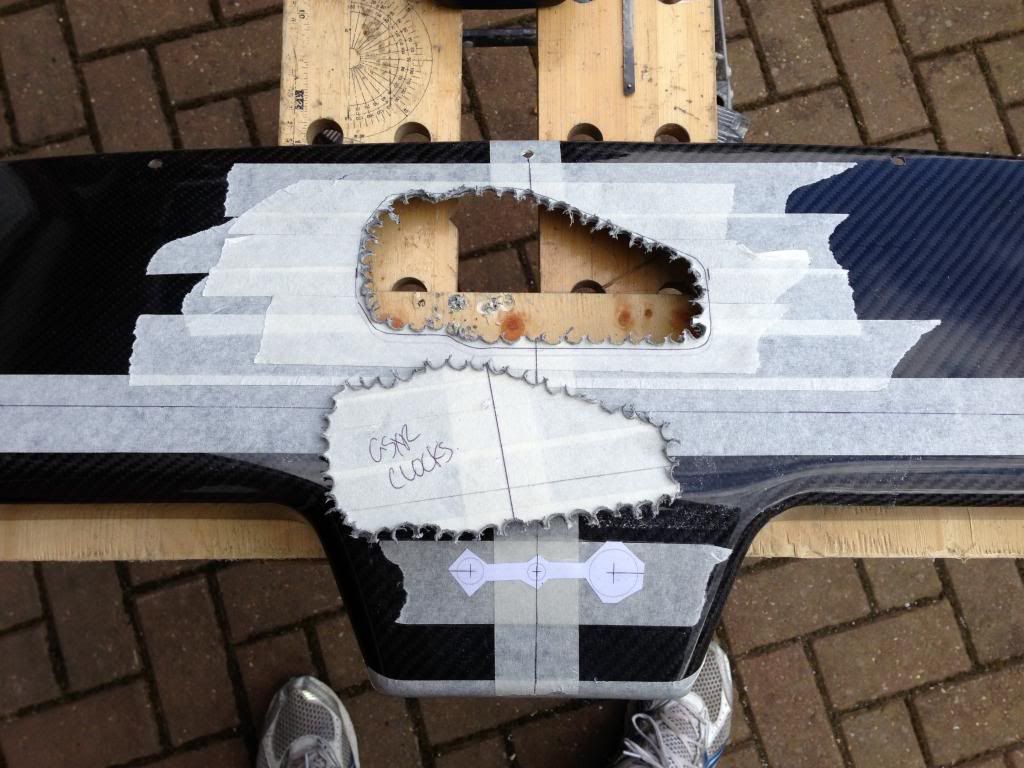
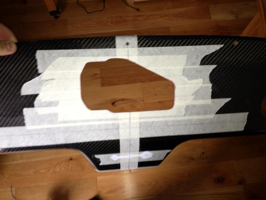
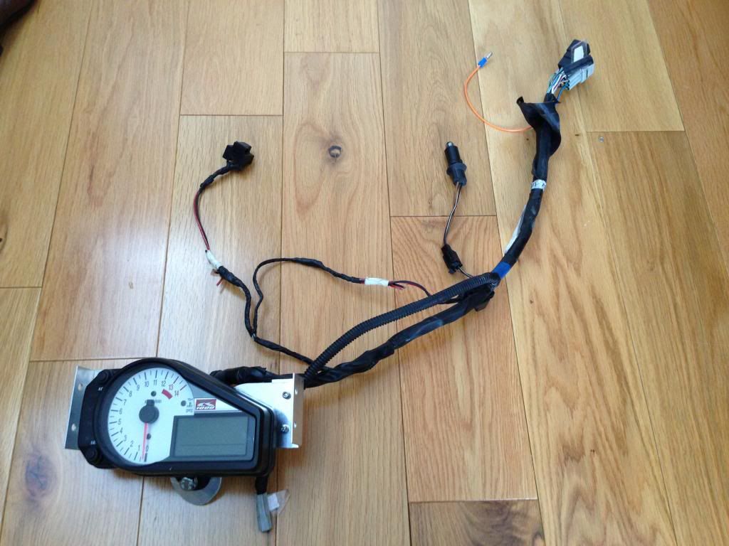
Last job was to fix the mounting brackets that will hold the GSXR clocks to the back of the dash.  These were made from aluminium angle which was bonded on using PU adhesive.  Both surfaces were cleaned and a keying surface created by scratching with a screwdriver.  The brackets were glued and clamped and allowed to dry overnight.

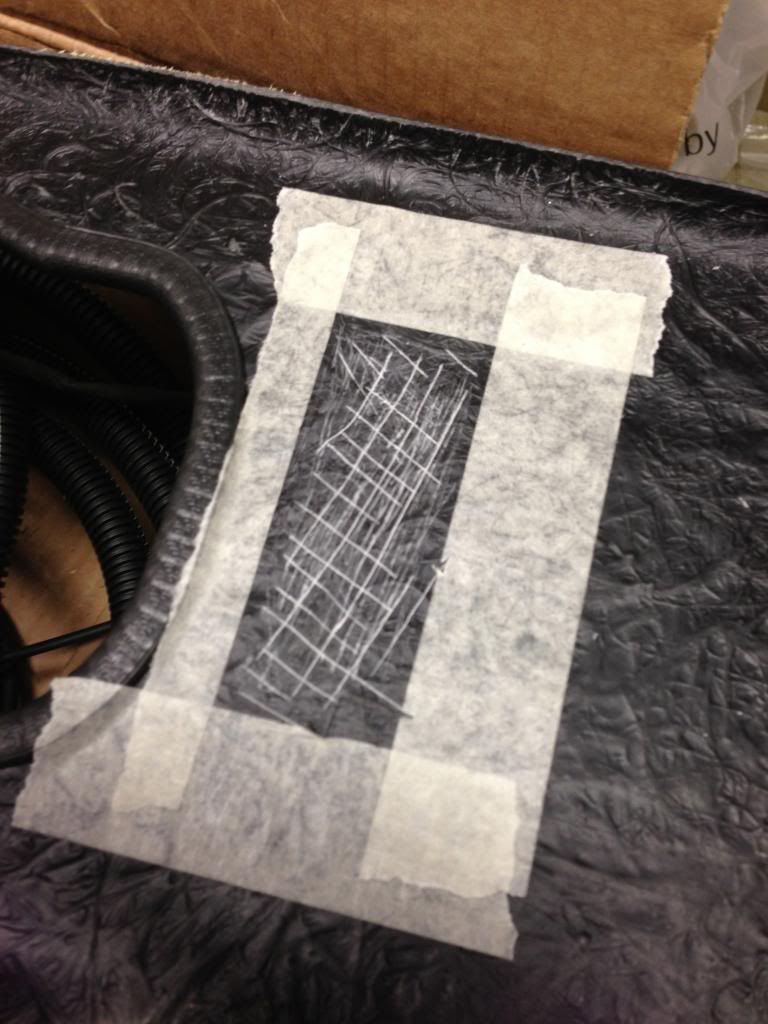
Area marked off and surface keyed

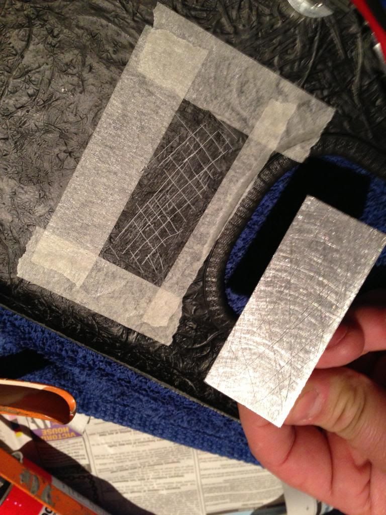
Aluminium surface keyed ready for adhesive

Brackets glued and clamped

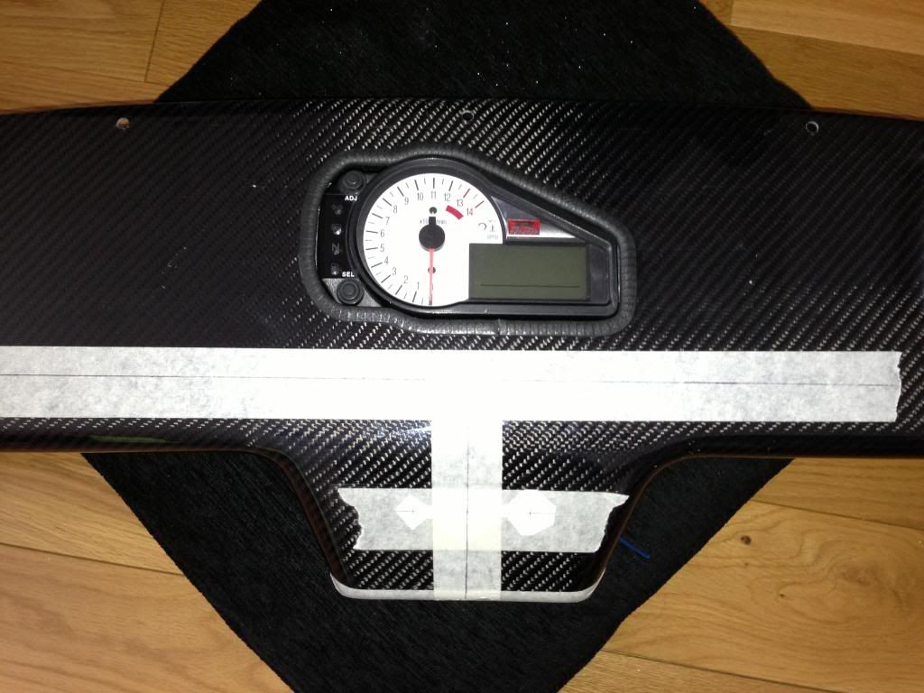
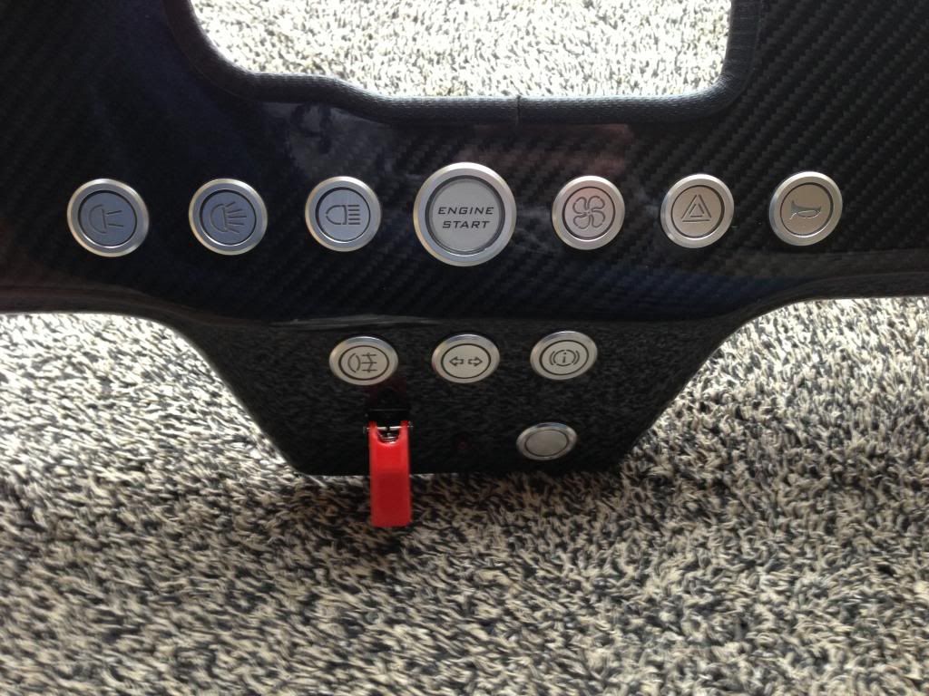
Clocks were installed the next day once the glue had dried.  Below photo shows the completed dash.


Saturday 30 March 2013

Electrics - loom end of 15 pin connectors


I spent the morning sorting out the other end of the 15 pin connector blocks.  This involved crimping the male pins onto all the loom cables noting which cable went where on my drawing.

I plugged all the male ends into the female connector so I could check everything was working before making the permanent conection in the 15 pin block.

This still needs tidying up.


Wheels arrived


My wheels arrived today!  I went for Team Dynamics Pro Race 1.2 13" with Yokohama A539 tyres in 185/60r13.

I fitted one of the rear ones to check the clearance of the handbrake springs.  I knew it was going to be tight, but was surprised how tight.  There is about 3mm clearance between the wheel and the handbrake spring and mechanism.


Friday 29 March 2013

Dash - Cutting out carbon dash and wiring switches


Today I completed the dash.  I started by cutting out for the clocks by stitch drilling, cutting out with a hacksaw blade and then filing carefully by hand to the required shape (shape taken from the template I made some weeks ago).  I then used some small edging trim on the edges ensuring it was pushed fully into the corners.  Doing this inside where it was warm helped with this.

Next I marked out all the switch locations.  It took a while to decide the layout but eventually settled on having the start button as the centre piece with lighting buttons to the left.... fog, fan and horn to the right... hazards and handbrake below, along with indicator telltale.  Reverse will be below all these.

I got my brother to draw out the switches on CAD so I could mark them accurately.  I proeceeded to centre punch the positions and cut out with a 19mm hole saw.  I then used a stepped drill to expand the holes for 22mm (30mm for start button).  I also cut out for the ignition switch, again 22mm.

Once cut out I sanded the hole edges with fine sandpaper, removed the protective masking tape and installed all the switches.  I then wired up all the switches according to the drawing I previously made and connected 2 x 15 pin connector blocks.  The idea is that the dash can be completely separated from the loom should I need to change or alter the switches.

This was the piece cut out for the steering column.  Used it as a test for the stepped drill to ensure it stayed central when drilling.  Worked perfectly!


Stitch drilled

Cut out with hacksaw blade

Filed smooth with half round file

Edge trim installed

The stepped drill bit.  Excellent bit of kit.

Switch location drawing on CAD, printed, cut out and stuck on as a template

Pilot holes drilled

Hole sawed to 19mm, stepped drilled bit used to get to 22mm for switches, 30mm for start button

Bottom holes - 12mm for toggle switch, 8mm for LED, 22mm for savage switch

Switches installed!


Before I removed the switches from the timber template, I drew up a couple of drawings that identified where each cable would go to on the 15 pin connectors. This was needed for the wiring in the next step.


I daisy chained several earths together to reduce the number of earths needed at the 15 pin connectors

Complete!  Two 15 pin connectors for all the wires to the dash switches including ignition


Sunday 24 March 2013

Electrics - Got the engine started!!!!


After a good few hours research and asking questions on Locostbuilders, Facebook and the Gixxer forum I final had some information.  Apparently the fuel pump relay wasn’t working due to the anti theft system that was linked to the original bike ignition.  Some modifications were needed to the loom to ensure the bike ecu thought the ignition was still there – I guess this stops people ripping wires out the ignition and hot wiring the bike.  I was told that MK had sorted all the resistors and diodes with the loom when they had it so still wasn't sure what was wrong.

I cut back some of the tape on the loom and found the orange/yellow and black/white wires along with what could be a resistor under some heatshrink – it looked like the necessary mods had been done by Steve at MK.  I used the ohm meter and checked the orange/yellow wire at the ECU – the resistance was 1.9 ohms, about the same as a dead short.  Something wasn’t right.

I wiggled the resistor around and the resistance seemed to flicker about before settling at 100.2 – the resister was 100 ohms so this was right.  It must have been a dodgy connection!!  I stripped the heatshrink back to find very sharp soldered ends which may have been poking through the heatshrink causing a dead short.  I put some extra insulation in there and redid the heatshrink.  Now it was always reading 100 ohms.

I plugged the ECU back in, turned on the ignition on and the fuel pump primed!  Small petrol leak at the throttle bodies due to the jubilee clips not being tight enough.  After this was sorted I tried again, operating the throttle by hand, and got it to start!!!  It ran for 5 seconds before I turned it off as theres no coolant in it yet.

Very pleased to get it running!!!!!!

I also shortened the bike clock loom and removed all the old wires from headlights and indicators.


MK installed resistor in the bike loom.  Note the sharp solder.

Loom to clocks before shortening


The blue/black wire in the middle is from the neutral light.  This is needed for the reverse, as previously mentioned, to ensure the reverse can only be activated when in neutral

Loom section after stripping out and shortening